Header Ads

Pulse width modulation of PIC Microcontroller and Mikro C


In this tutorial we will learn Pulse Width Modulation(PWM) technique in microcontroller. Pulse Width Modulation use for control the output voltage. You can watch the video or read the written tutorial below.


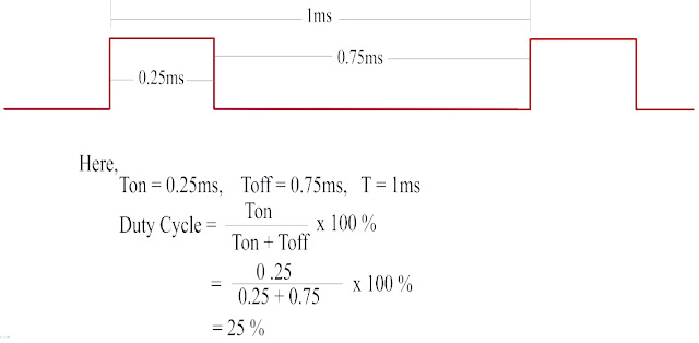
Pulse Width Modulation is the method to produce variable voltage and different duty cycle. PWM use for Led brightness control, DC motor speed control and generate different duty cycle frequency.
PIC16F877A

PIC16F877A microcontroller has two CCP(Capture / Compare / PWM) module.

  1. CCP1
  2. CCP2

Each Capture / Compare / PWM(CCP) module contains a 16 bit register which can operate as a:
  1. 16 bit Capture register
  2. 16 bit Compare register
  3. PWM Master / Slave Duty Cycle register.
Both the  CCP1 and CCP2 module are identical in operation , whit the exception being the operation of the special even trigger.


Circuit Schematic of PWM Circuit


circuit schematic

Different Type Duty Cycles


Relation Between Duty cycle and Output voltage

Output voltage = Duty cycle x Vout(max) 

                                Here,
                                          Vout(max) = 5V


                                 assume, 
                                               duty cycle = 25 %
                                               
                                                Ouput voltage = (25/100) x 5
         
                                                                        =  1.25 V 

                                 assume, 
                                               duty cycle = 50 %
                                               
                                                Ouput voltage = (50/100) x 5
         

                                                                        =  2.5 V 


                                 assume, 
                                               duty cycle = 75 %
                                               
                                                Ouput voltage = (75/100) x 5
         

                                                                        =  3.75 V 


                                 assume, 
                                               duty cycle = 100 %
                                               
                                                Ouput voltage = (100/100) x 5
         

                                                                        =  5 V 


Mikro C  Code:


Click the download button for source code and proteus file :
downlaod


No comments

Theme images by 5ugarless. Powered by Blogger.